
Install a Patch Bay and Remove Mains Hum Buzzing
Music Production Tutorial #7
This (now last) winter I was starting to install a patch bay into my studio and thought it would be a good idea to make a video to explain what a patch bay is for and how you could install one yourself.
VID HERE
There’s more detail (and waffle) in the video on how to install a patch bay but this write up will focus on the key elements of 1) what is a patch bay and what does it do and 2) how to install one in your studio.
It’s been a long time since my last post – sorry, I have been busy with my live sound and event business www.audiocrew.net.


…but now I’m on track again.
So What is a Patch Bay?
A patch bay is a way of easily connecting together the bits of gear in your studio.
Everything in the studio is plugged into the patch bay. With the use of small patch cables you are able to connect one piece of equipment to another just using the patch bay. This negates any annoying escapades around the back of the equipment plugging and unplugging things where you can’t see anything.
If you want to see how I built my studio from scratch click < here >
Do I Need a Patch Bay?
Possibly not! If you don’t have any outboard gear then definitely not but if you have a lot of items that you want to connect in different configurations then it’s well worth thinking about!
Mixers, compressors, gates, other processors, audio interfaces, mic preamps, keyboards, reverb and FX units as well as various other units can be connected together ad-hoc and at will.
It’s a fair bit of work to set it all up but there’s a great sense of achievement after soldering your own patch bay.
Where Can I Get One?
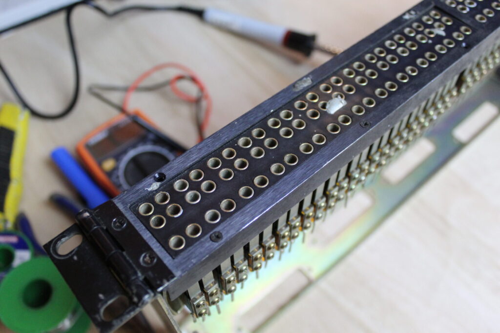
I got mine from ebay. I had to clean it up but it was easy to do and took about an hour. It came with a mixer I bought in 2005 but have seen these exact units (ADC 96+) for around £100. They have 96 connections so that should be enough for most project studios, otherwise you can get a second one!

Ideally you want soldered connections as this will give you the cleanest signal (assuming your soldering is decent enough!)
Digital patch bays are an option too…they are expensive but totally rad. You save the patching configuration in the computer and it’s automatically recalled each time you open the relevant project.
How Do I Connect a Patch Bay?
Hold your horses! There’s a few things to know about how to set up a patch bay and how to lay it out to suit a particular studio and workflow.
I’m Not Normal.
Normalling (not normalising) is an important concept in the patch bay. This is best explained with an example:
In my studio I’d like my SSL Fusion permanently fed by output 3-4 on the audio interface. In turn, the outputs of the SSL Fusion I would like to be permanently routed to inputs 3-4. This gives me the easy option of feeding any source through the SSL Fusion at will using Logic’s I/O plugin. Great.
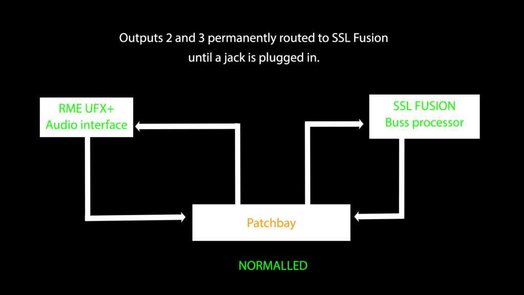
This is where normalling comes in. We can normal these connections on the patch bay. This means that even without any patch cables used these connections will be made.
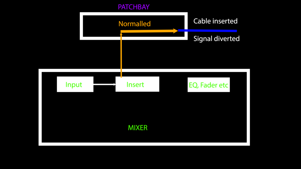
When we plug in a patch cable to any of these sockets, the normalled connection will be broken and the signal can be diverted elsewhere.
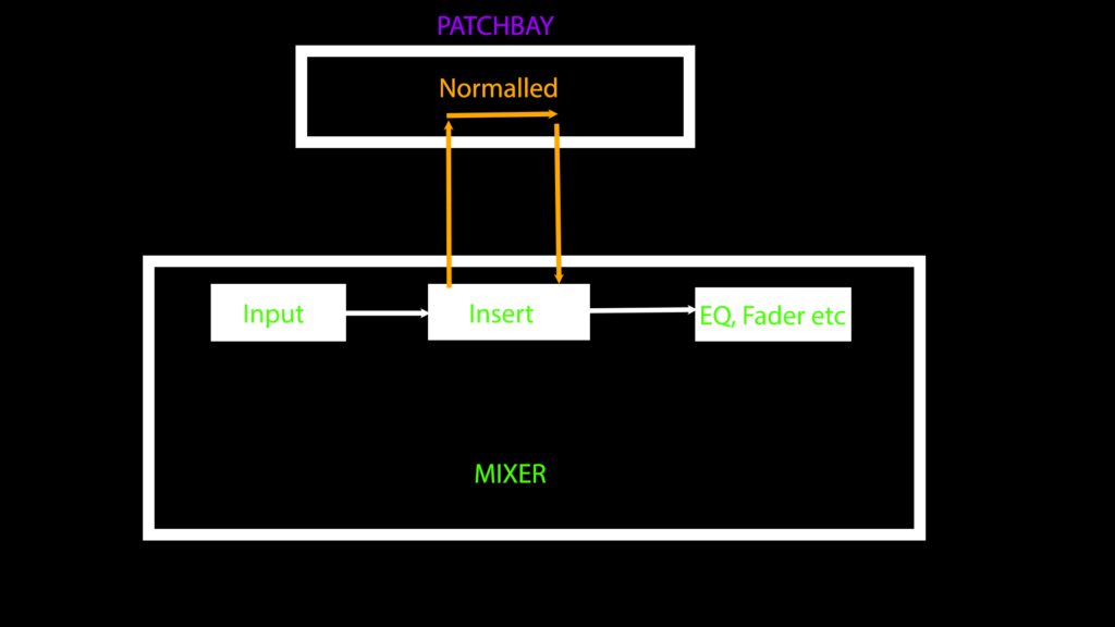
Here’s another example with inserts. These would make sense to be connected together all the time until you want to add a compressor or other processor into the channel path:
More Than Half-Normal
There are a few different types of normalling. The convention on a patch bay is to have the outputs at the top and the inputs at the bottom.
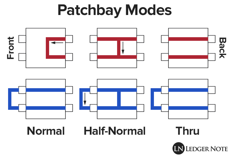
Full normalling
Means that when you plug into either the input or the output it will break the signal flow between the two.
Half normalling
Will only break the connection when we plug into the input but not when we plug into the output. This means you can use the patch bay as a kind of splitter and divert the output off to somewhere else while still keeping the normalled connection.
Thru
Thru means there is no normalling and a connection will only be made when a patch cable is inserted.
I went for full normalling as my patch bay had a third row which can be used to send the output elsewhere without upsetting the normalling. The top and bottom rows of jacks are permanently connected. This is regardless of wether a jack is plugged in. You can use the lower tier to divert signals elsewhere. I think of this third row as a splitter.
You can say this patch bay is both fully normalled and half normalled. At least that is the net result.
Ground Loops, Mains Hum and Earths.
A ground loop is the annoying buzzing sound you sometimes get with audio gear. It happens when there is more than one path to earth.
The electrons would ordinarily make their way to earth in an orderly fashion but, if there are two paths to earth they can get confused! This will produce awful buzzing sound as they push and shove one another, looking for the the best exit!
This really is a terrible shame! This buzz will end up all over your recordings as well as being irritating in the first place.
Generally it is because two pieces of audio gear are connected together with a cable that contains an earth. This is shown below.
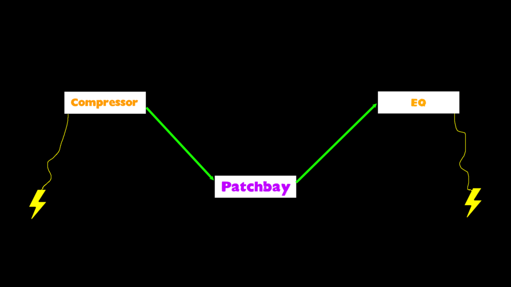
As each piece of gear is earthed via a mains plug, any point in the cable or circuitry has two paths two earth. The red dot in the diagram below indicates an electron and its path to earth.
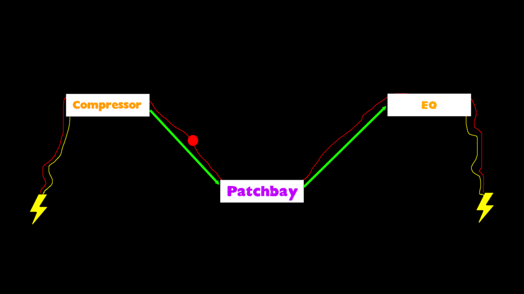
The simple way out of this is to break the earth at some point so that at any one point there is only a single path to earth:
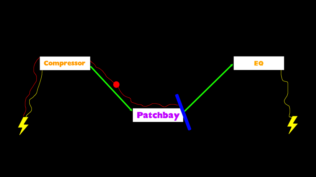
This patch bay actually was set up for that already. The input side only has two solder points, the earth has been left out and only the hot and cold are connected. The blue line above shows where the earth loop is cut.
All that remains is to neatly cut back and insulate the earth so it doesn’t inadvertently touch anything else.
Planning the layout
It’s worth really spending some time planning exactly how your patch bay will be laid out. You’ll need to consider what gear should be normalled of course. Essentially, you’ll want all your most used connections permanently routed. It’s worth thinking about any other connections that might not be permanently routed and where is convenient to keep those. When you know where your gear will physically be, loom lengths and connection type will need to be planned.
Keeping to the convention of outputs at the top, inputs at the bottom is best. That will help keep things simple while you decide what bit of gear will go where!
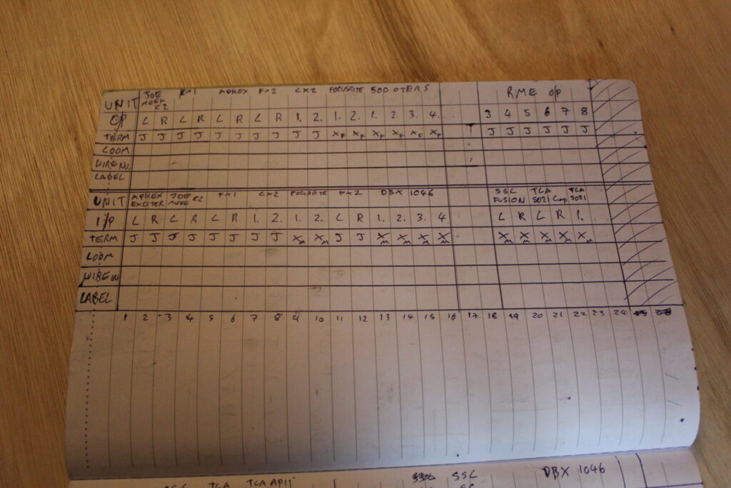
Once you have a rough plan, I’d advise drawing it up in neat. You might want to refer to this in a few years time when you have some new gear to add or when you want to re-jig the studio so keep the plan safe! It will also be your guide for soldering. Keep note of the connection type, gear that it relates to, the loom number as well as the patch bay number. It can easily get confusing!
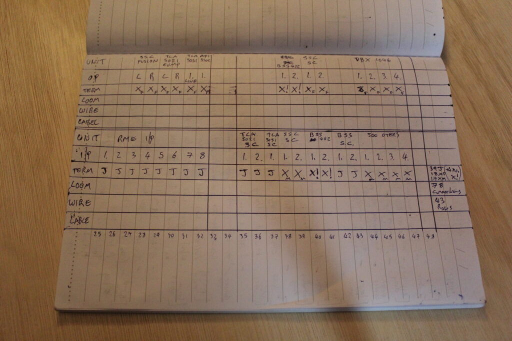
You can see from the above couple of pictures that I have my SSL Fusion, TLA 5021 and TLA 5051 all permanently connected to the inputs and outputs of the sound card. Now I can quickly divert signal in and out of there from Logic X at the touch of a button.
Installing Your Patch Bay
Once you have the plan and you have all your jack or XLR plugs of the correct sex, it’s time to settle down and do some soldering.
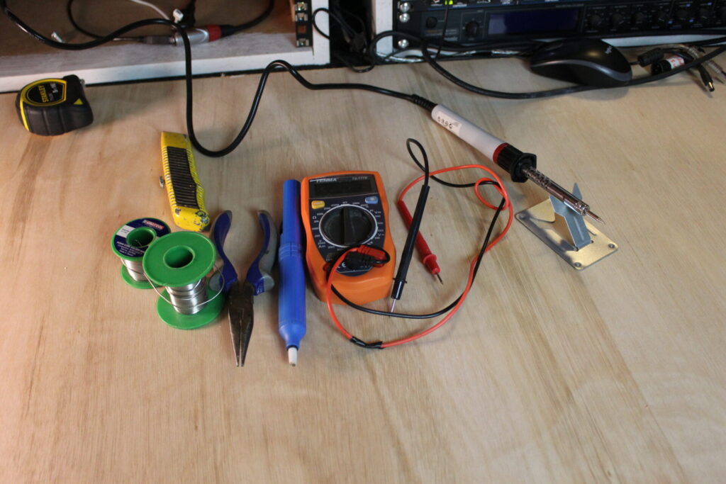
It took me ages! A really long time. Seven hours in and my brain had melted completely. I was about halfway through then. I do feel satisfied tough. It’s about 500 solder joints or thereabouts! Now it’s done though it’s really quick and easy to send the signal around different pieces of gear in the studio.
For some practical advice on soldering, take a look at the video which is time stamped on Youtube.
Check out my tutorial on How to fix crashes in Logic X <click here>
See you soon and happy 2023!